October, 2007

|
| We plan to host a builder's workshop in Tucson between Christmas and New Years Day, 2007. |
Some "Daffy-nishuns"
- Glide Distance - Half the distance from an airplane's present position to the nearest emergency landing field.
- Range - Usually about 30 miles beyond the point where all fuel tanks fill with air. Deduct 25 percent if listening to a Navy pilot.
- Roger - A verbal response that you use when you're not sure what else to say.
- Bank - An institution that holds the lien on your airplane.
- Stall - A technique used to explain to the bank why your airplane payment is late.
- Steep Bank - A bank that charges a pilot more than 10% interest on his airplane loan.
Dave Christensen's conventional gear Marathon--great design innovations and workmanship
In our last newsletter we covered Gary Rene's fixed-gear taildragger, and here's another fine example of the same type.
Builder Dave Christensen sent email updates and photos of his Marathon project that we were unable to squeeze into our last newsletter, so here goes:
Hi Eldon,
I will take some pictures today of my current status. I am using an RV-6 engine cowl on my Marathon which has about 1 1/2 degrees of right thrust angle built in.
To get this the RV engine mount has the dynafocal mount offset 1/2" to the left, which puts the prop on the aircraft centerline. Will this setup work for the Marathon or will I experience yaw problems in cruise? [I don't believe there will be any problem-Ed.]

|
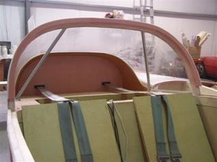
| This picture is an optical illusion-stare hard at it for a few seconds and a red and white biplane will mysteriously appear! Nice wraparound rear window, Dave. |
|
| Wraparound rear window close-up. |
I expect delivery of my RV-6 cowl (James Aircraft Holy Cowl with the round inlets) in a couple of weeks. They have a nice profile photo of it on their website.
If I take the picture and hold it up in front of the fuselage at a distance I can see that it fits perfectly. The top of the cowl is a 7-degree slope. If I set my instrument panel 8" above waterline 00 the 7 degrees puts the crankshaft CL just 1" below the top mount bolts.
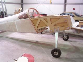
The angle of the bottom of the cowl matches up with the angle of the bottom of the fuselage and gives just the right clearance for my fixed fuselage mounted gear to flex downward and to hide the mounting bolts.
I added a couple of extra engine mount fittings at the bottom of the firewall (shown on next page) instead of using the horizontal tube shown on the plans which probably would flex and not take much of a load.
|
| How she sits. Right pretty, I would say. That's a very smooth rear canopy profile blending into the fuselage "turtledeck"... |
I am also using an RV-6 canopy. I designed the forward canopy to raise up and swing over and forward on four arms that form a parallel-ogram. These will be hidden under the edge of the canopy frame in the closed position.
I found a couple of standard gas springs at Overton's that should work well to push the canopy up evenly on both sides. I think this will work well.
|
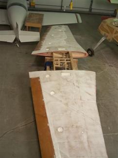
| Dave's wing assembly, inverted, pointing towards his award winning KR-2. |
I am ready to construct my engine mount now. I plan to use the Lycoming 0-360, 160 hp engine. I have estimated my C.G. location and it looks good with a metal fixed pitch prop for two 180 lb people and 50 lb of baggage.
|
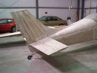
| ...and Dave's fin strake also blends into the fuselage very nicely just aft of the rear window. Note RV-6 type spring tailwheel. |
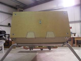
|
| Dave Christensen's mounted landing gear and additional firewall hard-mount points |
I will have to use ballast in the baggage compartment to bring the most forward C.G. location to aft of the 22% position for one person and no baggage operation due to the limited CG range resulting from the short MAC of the tapered wing but that's okay. My plane fully loaded should be a little over 1600 lbs.
Thanks for your interest in my project. I am very excited about it!
Dave
Dave Melby and others innovate as they build. And here are some pictures we promised last month!
Last month we promised to show you more photos of Dave Melby's design innovations. Here are a few of his breakthroughs.
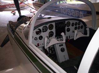
|
| Yes, you can replace control sticks |
with yokes. Just ask Dave Melby!
One of the big changes Dave Melby has made is to install a pair of very attractive control yokes rather than stick controls in his first Cavalier. Looking back at the picture that I took last June, his yoke controls just look like they belong.
While both types of controls have their friends (and their enemies), let's suffice it to say that you can go with whichever one suits your fancy. Hey, it's your airplane, right? Made for you, and not for someone else?!
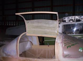
|
| Melby's simple yet elegant method of hinging his gullwing type entry door on the Cavalier. |
Some time ago I was working on a design for a gullwing type door. But I got bogged down as I struggled in my mind with a good way to hinge it on top. It never occurred to me to do it the simple, effective way that Dave Melby handled this, as shown in the above photo.
Why of course! "We don't need no stinkin' hinges!" Just a couple of pins collared into those solid cockpit bows and you're all set! (Now why couldn't I think of that?)
But there I was, stuck in my paradigm of having to fabricate some type of external hinge. It would have to be sturdy, maybe machined aluminum? And then of course since it would stick up in the airstream, I should devise a means of recessing it into the fiberglass, no?
I would guess that, by the time I had "engineered" all of this in my mind, my assembly would be about ten times as difficult to fabricate, and maybe four times heavier, than Dave Melby's simple door pivots.
Maybe Tony Bingelis had covered this in one of his wonderful sportplane builder books, I don't know, but it just makes so much sense! One of those things where you hit your forehead and say, "I should have thought of that!"
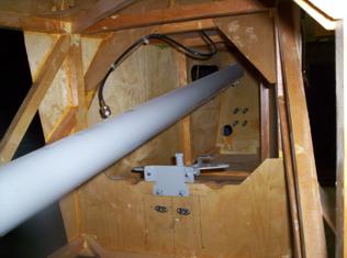
|
| Cable-to-control-arm translator for rudder (gray piece just below the large tubing) |
Another cool idea is Melby's rod control to the rudder. His rudder cables end at the bellcrank shown above, onto which a control rod end is bolted. The rod then extends back through the fin spar to a single rudder horn.
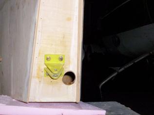
|
| Rudder control rod comes through a hole in the back of the fin spar. |
This last idea (see next column) is a little harder to visualize because the part that I photographed is sitting up on a shelf behind Dave's airplane.
What we're trying to convey here is a way to secure your horizontal stabilizer to the fuselage frames that allows for adjusting, if necessary.
The stabilizer is mounted at a slight negative angle of attack, a degree or two. But if it's glued in place you're stuck with it, whether it's a bit of nose up or nose down trim, as a result.
By allowing for fasteners to be put into the stabilizer spars, you can change your setting up or down as you wish, to trim your airplane perfectly.
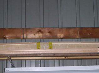
|
| Horizontal stabilizer has receivers for screw mounting rather than gluing it onto the fuselage bulkheads. |

More right rudder? Or more right thrust? What'll it be?
In our lead article about Dave Christensen, he mentioned that he is going to install his engine canted to the right a bit, to account for the left-turning tendency (p-factor and all that stuff).
Some of you may wish to handle it that way. Others will want to effectively build in a couple of degrees right rudder by moving the leading edge of their vertical stabilizer to the LEFT. (You could do the same thing by canting the rear part to the right but that's a little harder to do.)
The good news is, you can do it either way. It doesn't make any difference at all. Just don't forget to do it, one way or the other, or you'll always have to hold right rudder for the rest of the years you fly your airplane, even when straight and level!
© 2010, Mirage Aircraft, Inc, Tuscon, AZ


