February, 2006
Please note new email address-Editorial
Having finally found a (smaller) Internet Service Provider whose Technical Support is located in the U.S. as opposed to India, I have changed my ISP.
In addition to the language problem when I needed technical support (some of their staff were truly unintelligible!), my former ISP insisted on charging me $1.00 extra a month for a paper invoice, and then never sent me any invoices!
Instead they would wait until payment was "past due" and then send me an email or call me on the phone to ask why I hadn't paid.
It wasn't the amount of money so much as the principle of the thing. They were also incapable of making any corrections to my account to credit me for past erroneous charges either.
I battled with them for way too long, had too much frustration (ordinarily I am a patient person in this regard), and so I finally dropped them, e.g. mindspring.com. Good riddance!
By the way, I can recommend my current ISP copper.net without hesitation, in case you are interested in spending your money for Internet services provided solely by a North American company. They haven't joined the cheapskates with their technical "service" overseas.
By the way, I tried Juno.com for a short time and had the same problem with foreign technical support, in fact it was worse than Mindspring! I understand that AOL.com has taken the cheap Indian route with their technical support also.
I don't mind airing my dirty laundry on this one, since the outsourcing wizards who advise U.S. corporations are, like the lawyers, ruining everything.
I say, "If you don't demand excellence, you'll never get it." Like my recent experience buying a new pickup truck-their incompetence almost cost me $3,836.00! But that's another story. Ed.
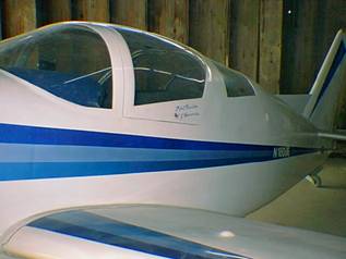
"A thing of beauty is a joy forever!"
|
| How refreshing it is to pause and look at Jim Glencross' beautiful Celerity once again! |
Weighing your project airplane-the right way!
Or, "Honey, have you seen my bathroom scales?"
Part 2 of our "how-to"
In our last issue we gave you an introduction to the proper weighing of your airplane project to determine how much useful load you're going to have, and to be able to figure out your CG (center of gravity) conditions before flight.
We'll finish off the topic this time, including a hypothetical situation that will hopefully guide you to relatively easy weight and balance determinations.
Setting up
Let us assume that you have borrowed the five bathroom scales from the wife and neighbors. Let us further assume that you have taken some care to calibrate the scales against each other.
Anyhow, we are now ready to actually weigh the airplane, or your airplane project (sans engine). This is really the easiest part. The calculations that we must do afterwards will require a little more work.
Bathroom scales are not known for their accuracy, so one way is to set a known, true weight on the scale and note the scale reading, then make corrections to the scale as needed. So at this point you have the left and right main gear, respectively, resting on a board across the scales, with the boards shimmed level across the scales. Note, this is very important in order to get accurate weights. You can place your shim boards under the scales rather than on top to make things simpler, whatever works for you.
Remember to weigh any boards or shims that you have used on top of the scales and then subtract these weights from the readings!
You CAN get by with just two scales, weighing each wheel individually in turn by re-leveling the airplane each time you move the scale under another wheel, it's just more time-consuming.
Of course, you'll need some small ramps to move the airplane atop the scales and/or leveling blocks each time. And don't try to move it by shoving someplace on the airframe. It's easiest to move it by getting down on your knees and turning each wheel by hand, which may require a friend or two to help you get it on the scales.
Now we will further assume that you have drawn the locations of the weighing points on the shop floor, as well as the location of the front face of the main wing spar, the lower edge of the firewall, and other locations as you go along.
Here is a hint for marking the correct fore-and-aft locations of your landing gear. Set a square on the shop floor up against the front and the rear of each axle, respectively, noting these locations on the floor. Then measure to the center of each pair of marks for the exact centerline and these will give you the official points to use for each datum line.
Hopefully the first time you do your weighing exercise is before you have fabricated your engine mount, so you will be free to locate the engine fore or aft as needed in order to balance things properly. Also because that's the order that we are going to do this in our exercise!
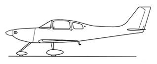
Approximate datum and arm locations
|
| Example only-not for field use |
But fear not, we will walk you through a set of calculations so you can see how it's done. Microsoft excel works great for this but so does a hand-held calculator, or a good head for math.
I have conveniently included a simplified layout sketch of the landing gear in relation to the datum for a Mirage Marathon (above), but please be advised that you will have to measure your own landing gear positions relative to your airplane's datum line! Do not rely on this sketch.
Locating your engine-alternative methods
In today's lesson we have an airframe that is essentially complete, ready for installing the engine, prop, spinner, and cowling. The problem is, we don't know yet how far we should mount the engine in front of the firewall. All of our staring at it, head-scratching, and nail-biting isn't going to solve the problem, so we must find a practical way to do this.
There are two methods for locating the engine position, "static" and "dynamic." What we have been talking about so far is a combination of the two. The weighing of the airframe ("dynamic" weight and arm determination) is followed by calculations. ("static" approach)
However, you can use the dynamic method for greater accuracy, if you wish, by placing sand bags to represent the weights of the engine, pilot, passenger, baggage, fuel, etc.
Here is one builder's suggestion:
Set up the aircraft in the proper weighing configuration, leveled etc. Construct a horizontal beam and attach it to the airframe, projecting out over the engine area. (Ed.note-This beam may be attached to the engine mounting brackets at the firewall.) Be sure to allow for the weight of the beam and its arm in your CG calculations.
Fill sandbags to represent the weight of the engine and cowling and hang these on the beam. Use another sandbag hung further forward to represent the weight of the prop and spinner, another bag or bags for the pilot, other bags for fuel, instruments not yet installed, etc.
Adjust the engine weight fore and aft on the beam so that when there is 1/4 fuel in the tanks and a pilot in the cockpit, the aircraft CG falls about in the center of the allowable CG range, or "envelope" as determined by the weights and calculation.
I am told that the center of mass of a pilot or passenger is approximately 2 inches behind that person's navel or "belly button" for purposes of calculation.
At this point the builder's suggestion ended as it was intended for determination of the fore-and-aft engine location only. However, one could carry this exercise further, to wit:
Now add full fuel tanks (more sand please), no baggage,and a light-weight pilot (say 120 lbs.) and check the aircraft weights for forward CG limits.
Next check for aft CG limits with a 180 lb. pilot, a 180 lb. passenger, minimum fuel (1/4 tank), and 60 lbs of baggage.
Recheck your weights and calculations and there you have it!
I don't know how many of you would want to do it, but this procedure will work to verify that your airplane meets the weight and balance requirements.
Plus, it would give you a lot of good exercise moving all those sand bags around!
The most commonly used method
Using the "easy" method, when we weigh our airframe (no engine or prop yet) we might get a set of numbers that looks like this:
Marathon weights (aft of firewall)
Example only, not for field use
| Weight (lbs) | Arm(inches) | Moment(in-lbs)
Weight Arm Moment
(lbs.) (ins.) (in-lbs)
|
|---|
| Left main gear | 342 | 68.75 | 23,513
|
|---|
| Right main gear | 343 | 68.75L | 23,581
|
|---|
| Tail position | 73 | 211.5 | 15,440
|
|---|
| Wt/Moment Totals | 758 | | 62,534
|
|---|
| Cg location | | 82.5 in. |
|
|---|
(We can also combine the two lines for the main gear, since they're on the same datum line. We would just put a total of 685 lbs. down and use the same arm, 68.75 inches, to give a combined main gear moment of 47,094 in-lbs.)
At this point the airplane's CG is calculated by dividing the moment, 62,534 in-lbs, by the weight, 758 lbs, to yield a result of 82.5 in.
Therefore the center of gravity of this airframe right now is some 22.5 inches aft of the main wing spar's front face, back in the baggage area. (82.5 minus 60) However, this CG point will surely move forward once we hang an engine out there!
I have a table of Continental and Lycoming engine weights which shows that the Lycoming O-320 E2A weighs in at 277 lbs. with accessories such as mags, starter, etc. all included. I have weighed a completed Celerity fiberglass cowling and it came in at 30 lbs. I will assume a weight for a wood fixed-pitch prop and spinner at 20 lbs.
Let's plug in the engine, prop, spinner and cowling at some estimated arms just for purposes of running some test calculations and see where we end up. We will also put 8 quarts of oil in the engine and add a battery with cables and a battery mount.
Estimated Marathon weights, oil and battery
Example only, not for field use
| Weight (lbs) | Arm (inches) | Moment (in-lbs)
|
|---|
| Main gear (both) | 685 | 68.75 | 47,094
|
|---|
| Tail position | 73 | 211.5 | 15,440
|
|---|
| Engine | 277 | 10.00 | 2,770
|
|---|
| Oil (2 gals) | 15 | 16.0 | 240
|
|---|
| Battery, cables | 25 | 26.00 | 650
|
|---|
| Prop, spinner | 20 | -4.00* | -80
|
|---|
| Cowling | 30 | 16.00 | 480
|
|---|
| 1,125 | | 66,594
|
| Cg location | | 59.2 in |
|
|---|
*Arms located forward of the datum are minus
Once again, dividing the moment by the total weight gives a CG location of 59.2 inches. This is just forward of the front face of the main spar by a little less than one inch. At this point we will determine the allowable CG range for this aircraft and then see how our proposed CG fits in.
|
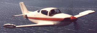
| Larry Burton, flying his new Celerity over Klamath Lake in 1985. As the designer of your airplane, imagine all the weight and balance work he had to do! |
Determining the desirable CG range
First we have to determine the mean aerodynamic cord (MAC) of the wing. (I commonly refer to it as a "wing" rather than "wings," you can use whichever term you prefer.)
For a "Hershey bar wing" or rectangular wing-form such as you find on the older straight-wing Piper Cherokees and on Van's RV series, this is very easy to determine. Just measure from the leading edge to the trailing edge anywhere along the wing.
It gets a little bit more complicated for a tapered wing, but it is nonetheless possible to mathematically define the MAC value, and you can physically locate it along the wing somewhere.
In the case of the long wing (current design) Celerity and Marathon, the MAC is 51.375 inches from leading edge to trailing edge at a point slightly inboard of wing rib No. 5.
Good aerodynamic practice dictates that the aircraft's CG always remain within a range of 15 to 30 percent of the MAC. On the Celerity and the Marathon this CG range runs from a point 7.7 inches aft of the wing leading edge to 15.4 inches aft of the leading edge. (51.375 X 0.15 and 51.375 X 0.30)
This seemingly small range, some 7.7 inches total, is what we want to shoot for. With the completed airplane empty except for engine oil it is desirable to have the aircraft's CG located in the middle, or slightly forward of the middle, of the CG range.
Using simple addition and subtraction, we will want the empty weight CG to fall between 54.7 inches and 62.4 inches aft of our datum line. The center of the range, 58.5 inches aft of our datum, would be perfect.
Our calculated CG, 59.2 inches (above), is close to the optimum. Adjustments can be made by moving the engine forward, which also moves the prop, spinner, cowling, and engine oil mass forward. The battery can also be repositioned a bit if necessary.
Please note, for this exercise I just made up the initial weights on the main gear and the tail. These weights in no way represent real aircraft weights.
I now leave it up to you to do your own actual weighing and performing the CG calculations.
Checking extreme fore and aft loading conditions
To check the forward CG limit of our example we'll use a light weight pilot (located aft of the CG), and full fuel tanks (located forward of the CG).
Marathon forward-CG calculation
Example only, not for field use
| Weight (lbs) | Arm (inches | Moment (in-lbs)
|
|---|
| Aircraft | 1,125 | 59.2 | 66,594
|
|---|
| Pilot | 120 | 74.0 | 8,880
|
|---|
| Fuel (40 gals) | 240 | 54.0 | 12,960
|
|---|
| 1,485 | 59.6 | 88,434
|
We find that the forward CG will not be a problem because it falls within our range of 54.7 inches to 62.4 inches aft of datum. In fact, it's slightly aft of neutral, indicating we might have a problem here with the airplane configured the present way. Let's go on to the aft-CG determination.
For checking AFT CG limits we will have minimum fuel on board (VFR minimums plus a gallon and a half unusable fuel). We will also use heavier pilot and passenger, plus maximum baggage (60 lbs.):
Marathon aft-CG calculation
Example only, not for field use
| Weight (lbs) | Arm (inches | Moment (in-lbs)
|
|---|
| Aircraft | 1,125 | 59.2 | 66,594
|
|---|
| Pilot | 120 | 74.0 | 8,880
|
|---|
| Passenger | 170 | 74.0 | 12,580
|
|---|
| Fuel (10 gals) | 60 | 54.0 | 3,240
|
|---|
| Baggage (max) | 60 | 93.0 | 5,580
|
|---|
| 1,605 | 62.7 | 100,574
|
The result, 62.7 inches, does fall slightly aft of the rearward limit for this airplane (62.4 inches), although it's admittedly close. However, we should move the engine forward a bit and recalculate. Better this way than having to try and explain it to the FAA when we want to certify the airplane!
An alternate way to address this would be to decrease the maximum allowable baggage capacity and placard the baggage compartment accordingly.
As I said in the last issue of the newsletter, a slightly forward CG, say 57 to 58 inches aft of datum, would be preferable to one that's around 60 or 61 inches aft of datum.
Alterations to an airframe to compensate for these conditions are sometimes made by the designer, generally stretching the fuselage or increasing the area of the horizontal stabilizer and elevator. However, such redesign is not in the scope of this exercise. Such rework of the airframe requires the assistance of an aeronautical engineer.
Aircraft weight and balance help, like anything else, can be found on the Internet. Just make sure you know what you're doing-don't blindly apply whatever you see that someone else has done and written up for posting on the Web.
© 2007, Mirage Aircraft, Inc, Tuscon, AZ
